 |
||||||||||||||
Musings from Bridgnorth pattern-shopOccasional notes from the team of volunteers beavering away at Bridgnorth's Pattern-Shop. |
||
| December 2008 | ||
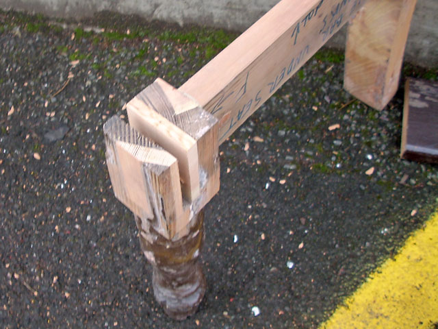
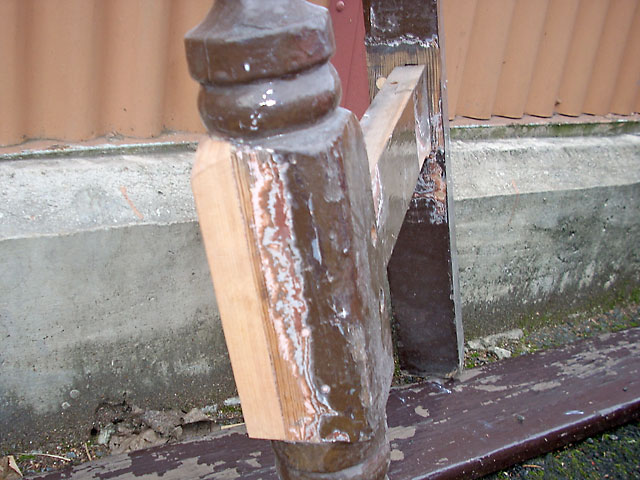
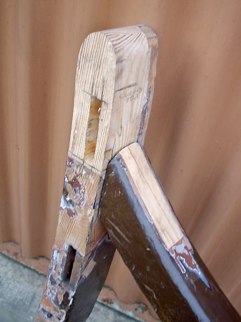
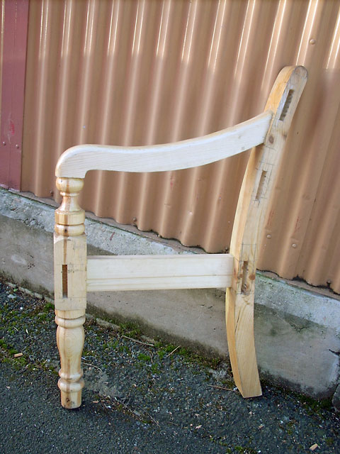
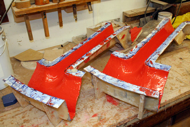
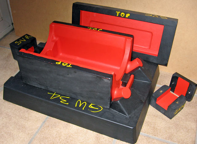
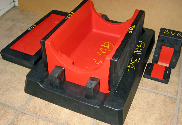
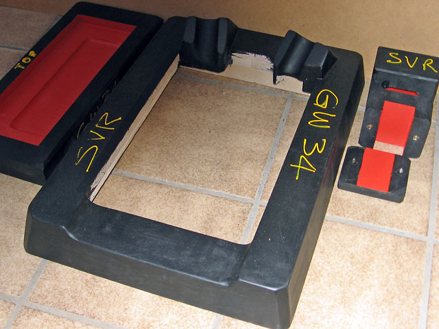
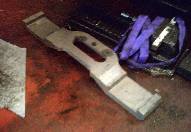
These pictures illustrate some of the extreme dutchmen Brian has needed to use to repair the Bridgnorth Station bench end and middle frame. To retain as much of its original provenance as possible the number of Dutchmen Brian had to fit has to be seen to be believed. Without modern adhesives the repair simply would not have been possible. These photos show one end and the middle frame.
|
Unfortunately the frame at t'other end was too far gone to repair so a replica was made from Pitch Pine using the rotten original as a pattern. Chris Thomas, Bridgnorth SM, was able to source enough of the same material to make the replacement end frame and carry out the repairs. No doubt in a few years it will be difficult to tell the whole end was replaced. Photos: Brian Oldford
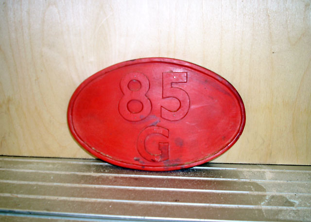
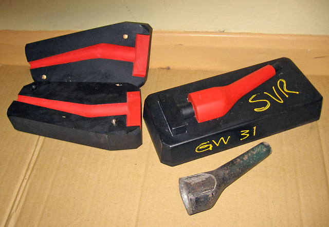
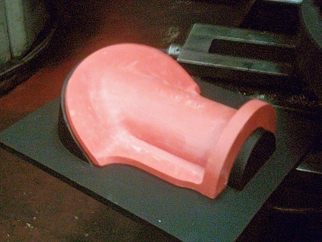
Without a nameplate, here's the pattern for the the most important piece on 82045! Check your ABC's for the location!
|
|
| November 2008 | ||
We haven't hibernated despite the shorter days! Here's a round up of some of the recent projects.
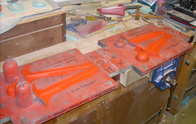
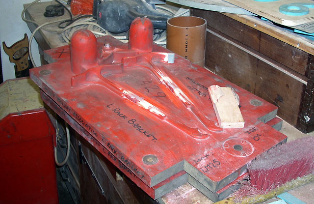
Neill Parker has busied himself refurbishing an LNER luggage rack bracket pattern that has lurked at the Cerdic Foundry for many months. (Cerdic are notable inasmuch as they produced the pattern and casting for the replacement cylinder for Taw Valley).
|
|
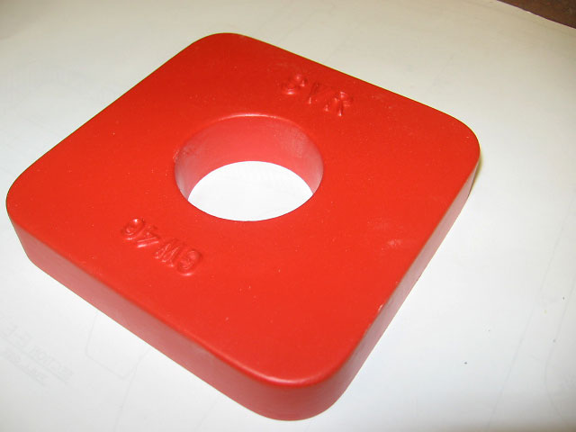
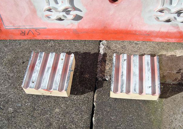
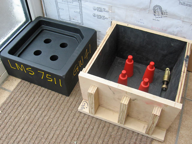
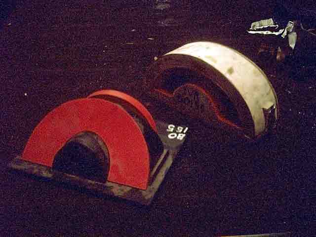
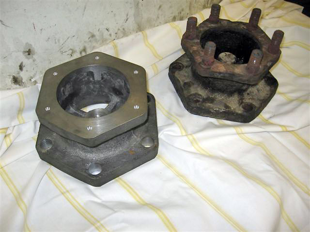
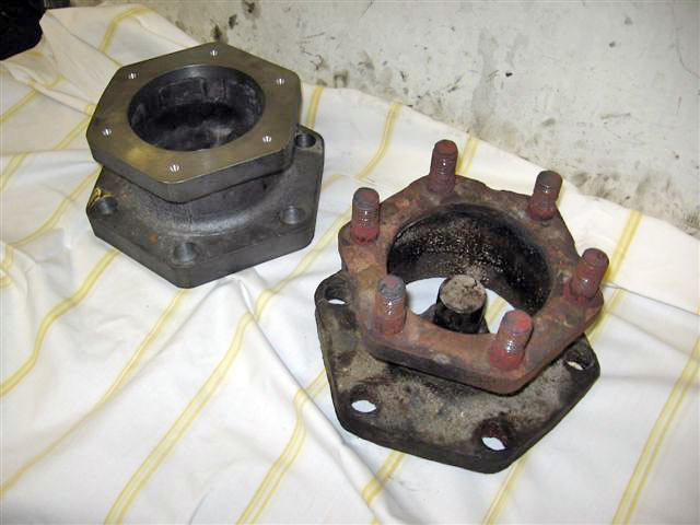
Recently produced by Gordon Woodruff are these Washout Plug Seats for 8XXXX class tank engine boilers. They are also thought to suitable for 75XXX too.
Humdrum but essential bits if we are to see 43106 steam. This is a pattern for a steel pipe flange for 43106 also made by Gordon Woodruff.
Brian Oldford (star of Heritage Railway and Steam Railway!!) is pressing on with the inner half of the driving wheel pattern for 82045 between a departure from his normal line of activity. He’s carrying out a major refurbishment of an all wood GWR bench. Unfortunately this suffered the ravages of the weather on platform 2 at Bridgnorth for many years. After major surgery and repair it will partner a similar style bench underneath the canopy on platform 1. The bench presently outside the Ladies has iron end frames and is more suited to residence on platform 2. |
August 2008 |
||
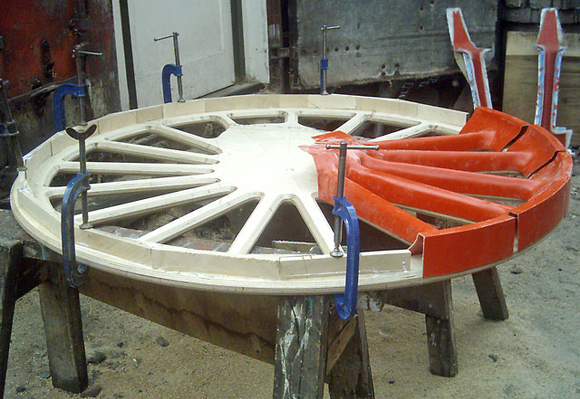
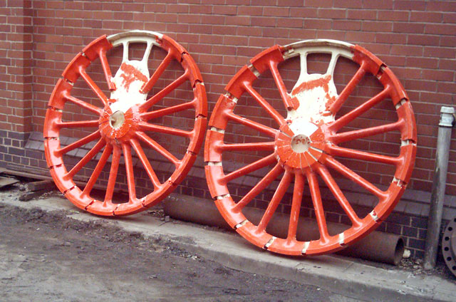
Brian Oldford continues to have a wheelie good time with 82045's drivers!
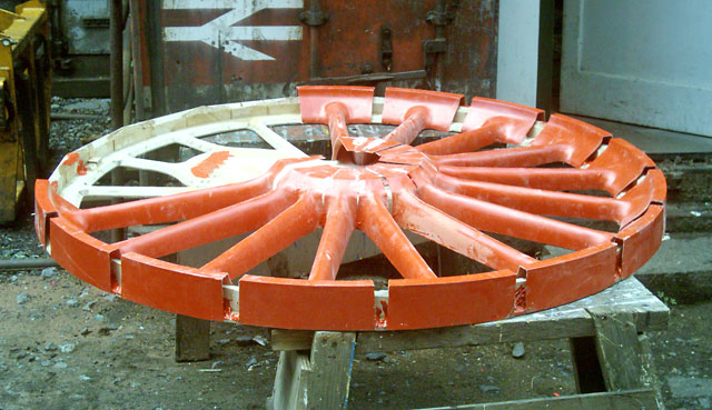
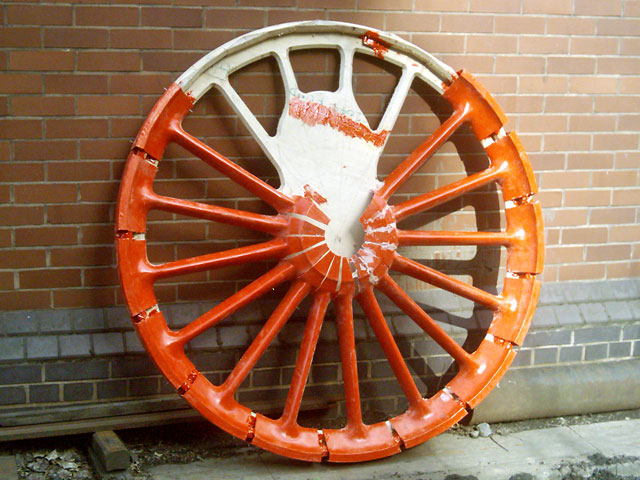
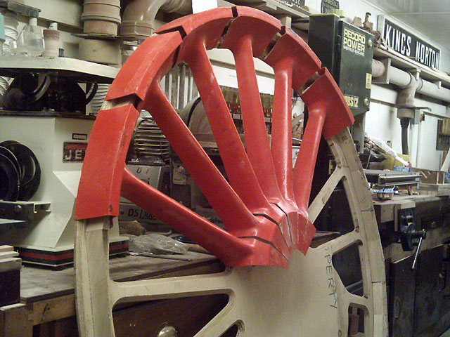
The two halves of the pattern with 7 of the 17 spokes mounted on the backing board. 12th July.
The weekend of the 2nd/3rd August saw the attachment of all barring the two shortest truncated spokes. The two photos above where taken on Saturday...
... and this one just before close of play on Sunday.
The moulds, above, for the two spoke halves have been gel coated awaiting the lay-up of the penultimate spoke. Once the spokes have been completed I'll commence on the crank-pin boss. And over the following weekend:
This leaves the following still to complete:
Which will keep us occupied for a while yet! |
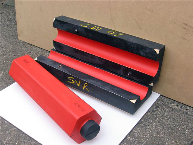
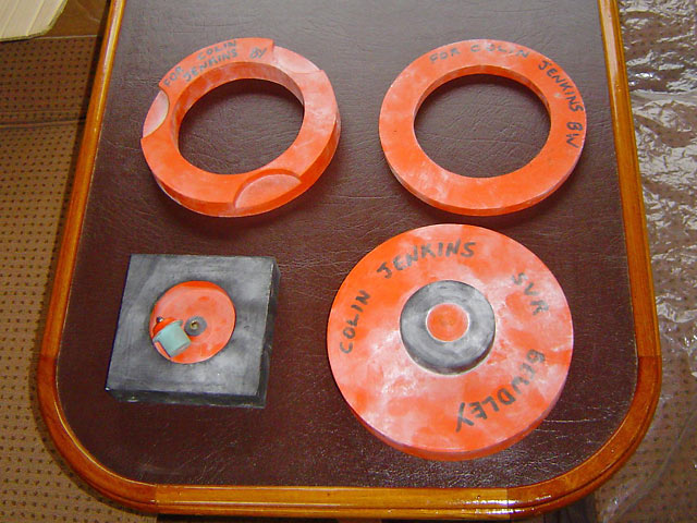
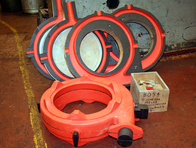
Last year we shewed photos of the Western type rodding roller brackets castings. Here are the pattern and corebox (these make the holes in the the foot to enable them to be bolted to concretes).
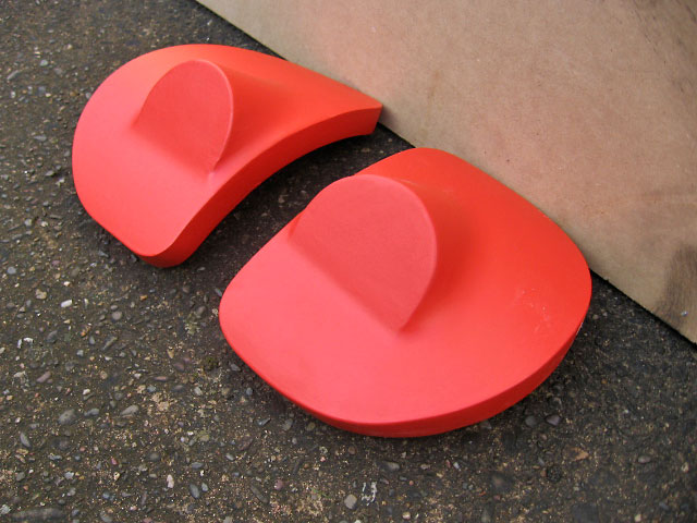
These couple of photos show a bracket pattern made by Gordon Woodruff along with an original casting. The pattern is to reproduce the bracket for the tables in LMS coaches like 7511. A pair of these brackets fit by the window to support that end of the table. The end nearest to walkway through the coach sits on top of a leg with the adjustable foot shown and made earlier by Gordon. Photos: Gordon Woodruff
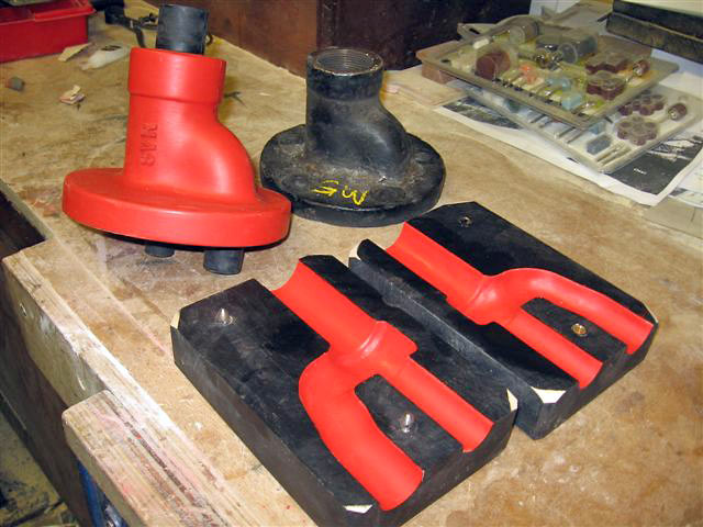
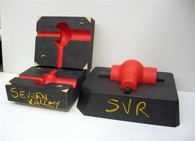
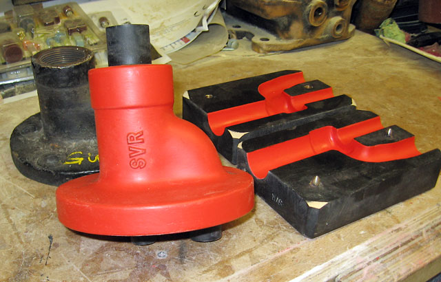
Another of Gordon patterns, this time for a Blower Valve Body for GW Panniers. Photos: Gordon Woodruff Geoff Midgley, when not working on the Venturer or WWWCo, is providing us with a very helpful pair of hands carrying out some of the filling and rubbing back on the 10mm monitor injector body. |
|
July 2008 |
||
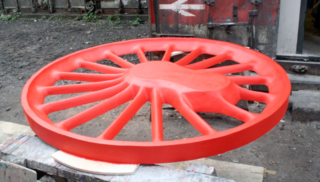
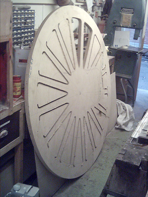
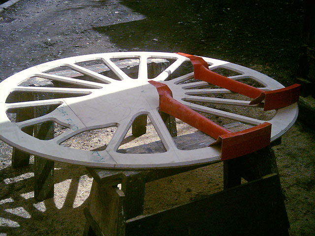
Brian Oldford has been busy re-inventing the wheel! For 82045 in this case. He writes: 30th June What started as two 8' x 4' sheets of 15mm plywood is now 2 discs over 5ft diameter with 17 holes appearing in them which correspond with the inter-spoke gaps along with a large pile of waste wood shavings. The piercings for the inter-spoke gaps are being made using our larger router fitted with a template following collar and a 1/2" router cutter. To guarantee the radii between the spokes at the hub and between the rim and spokes would be consistent I made a template for the collar to follow. The two 8' x 4' sheets were initially "cut and shut" to make the blanks large enough from which the discs could be made. These have then been temporarily screwed together so that both skeleton frames will be identical. I estimate that less than 30% of the original two sheets of birch plywood will be find its way into the final wheel pattern!" |
||
The two discs (temporarily joined to be identically machined) are 5' 0 1/2" diameter and thus could not have been made from a 10' x 5' sheet without doing a "cut and shut" job. I'm confident the router cutter will hold its edge to complete all the piercing despite the abrasive nature of the adhesive between the plywood laminations. Thanks to Titman Tools.” I'm using a standard 1/2" (12.7mm) router cutter (no bearing) inside the concentrically fitted 30mm collar. The collar simply slides along the template guiding the cutter rotating inside it. The template was made so it was exactly 8.65mm back from the wanted cut line. Standard formula (D/2 - d/2). (Note the 2 thou accuracy!). During a subsequent stage I will be using a bearing guided chamfer cutter to relieve the plywood to cater for the tumbleholm of the GRP mouldings. I will leave a few mm vertical edge on the ply to which the inside of the mouldings will be fixed.
I have yet to see how stiff the 15mm thick skeleton frame will be with only the moulding attached. If it isn't stiff enough I have a number of options: |
||
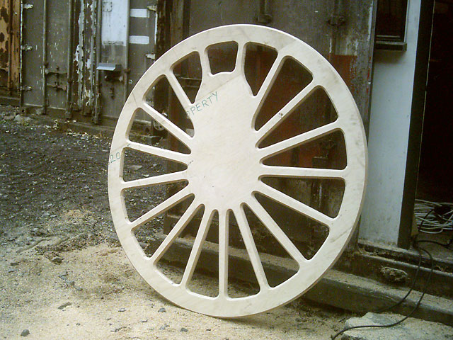
3rd July The pattern is a straightforward two piece split pattern with each half of the pattern is being built-up from the ply-wood datum. Although the theoretically perfect split line should include a joggle, the application of a little pattern-makers licence obviates the need for an oddside over 5ft in diameter. This is because inspection of a vertical section through the wheel reveals spokes that are slightly angled to the true vertical, i.e. cart-wheel fashion. This angularity makes for a more flexible wheel that is presumably less at risk when cast and provides a degree of resilience from road shocks in service." |
||
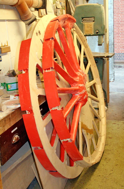
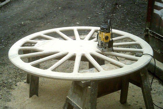
4th July Interestingly perhaps, is the fact although a wheel pattern is fairly large it isn't that complex. There are no complex cores to place accurately. Much of it is quite repetitive once you are set up. The tooling for the spoke segments took a bit of time to do but once done, production is a fairly simple process that's well documented on a number of web sites e.g. CFS Fibreglass Supplies. Similarly the addition of the stiffening pieces today is very much a repetitive process of cutting 360/17 degree mitres in strips of plywood made from the off-cuts (no shortage there then!) and glueing and cramping them onto the formers with PVA adhesive." |
||
|
5th July
|
||
6th July 8th July And, just in case I get bored, I have started studying and mulling over the drawing for the driving wheel horn block. It has a number of insidious undercuts that will require awkward coring or loose pieces.." |
||
| June 2008 | ||
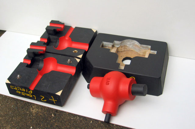
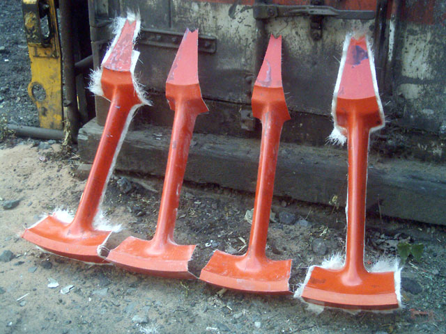
82045 now has 2/17ths of the driving wheel spokes! As you can see from the above photo the second pair of spokes haven't been rough trimmed to remove the surplus CFM (chopped fibre mat). The possibility exists that they may seem a little flimsy when assembled. If so Brian will fill the hollow cavity (very carefully) with expanding foam to reinforce it. The model/plug of the spoke and its corresponding "inner" half, shown below, had been coated with red flo-coat. This was sanded back with successive grades of abrasive to produce a really fine finish. Subsequently this was coated in PVA mould release agent; and today received two coats of white gel-coat prior to lay-up of 3 - 4 layers of chopped fibre mat. When this moulding is removed from the plug it will form the mould within which each of the 17 spoke halves will be moulded. For the technically minded;
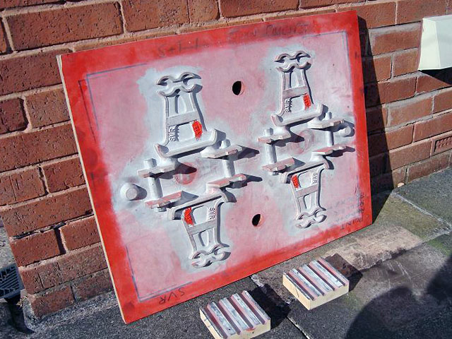
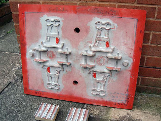
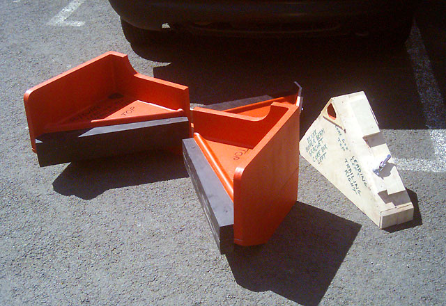
Work has also progressed with 82045’s buffer beam brackets. The coreboxes for both the left and right handed brackets are complete bar minor fettling and final paint. The patterns are almost fully assembled with only the coreprint portion of three of the four pattern portions to build before final fettling and paint. That little lot has pretty much used the two sheets of ply. The photo above shows the now complete patterns. |
This photo from Gordon Woodruff shows the pattern set to simultaneously make four of the ends of the table legs for LMS RFO 7511.
The pattern set for GWR water tank fillers made for Collett Saloon 9103. Meanwhile, between footplate turns Neill Parker is re-making some letters for the early GWR style step-plate for the stairs in Wrangaton Signal Box at Kidderminster for Dave Postle. |
|
| May 2008 | ||
GWR 13" combined ejector blower ring. Made back in the 1990s it has been in the pattern shop for additions of omitted features. When Brian created the drawing back in the early 90s from some photocopied scraps he then promptly ignored the relevant part of the drawing. Ho hum; to err is human! We've started the patterns for 82045's bufferbeam gusset brackets now, which remarkably are steel castings on the Class 3s. (To the best of our knowledge all other BR standards use fabrications for these components). |
Brian has also just started work on 82045's driving wheel pattern. Basically he's made a model/plug of one spoke (actually two halves since it is a spilt pattern) from which we will produce a pair of GRP moulds. In those moulds we will lay up the inner and outer halves of the spoke 17 times. Cue a remark about 16 1/2 spokes! |
|
| April 2008 | ||
Gordon Woodruff has recently completed the blower valve pattern for larger Stanier engines. Meanwhile the 10mm monitor injector body makes progress (slowly) towards completion. |
 |
|
| March 2008 | ||
The following photographs show the completed pattern, coreboxes and oddside for the pony truck axlebox keep for 43106. The observant may notice it is to be cast with two filler spouts. In practice one or the other will be removed prior to through drilling thus creating either a left or right hand variant.
|
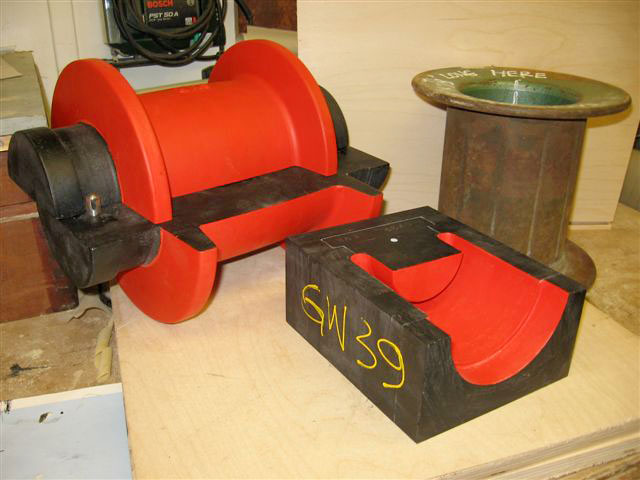
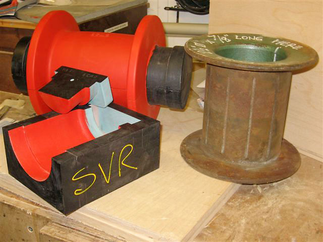
This is a pattern set for the LMS/BR water tank filler pipe end fitting alongside an original. Unexciting parts perhaps, but important in helping us to make sure the loos flush!
|
|
These are the two halves of the steam pipe clamps for 43106. The first is the inner portion complete with core (to deal with the flange undercut) and oddside to simplify the moulders task. The second is the outer portion which only required an oddside.
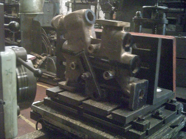
This is an 8mm Monitor injector body mounted on our small horizontal borer which was cast last year from a Bridgnorth produced pattern. The pattern and corebox set was made from a drawing (showing all the internal detail) produced by Charles Lamont who painstakingly reverse engineered an existing cast body. Honour for the machining must go to Graham Bennett using the vertical mill and small horizontal borer to get to this stage. An idea of some of the internal galleries can be seen in the photographs of the coreboxes for the 10mm Monitor injector.
|
For those that missed the first episode in horn ties these two photographs show the two new castings to replace the cracked ones removed from 43106.
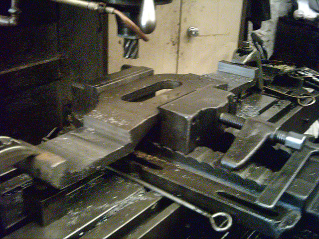
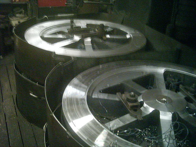
No credit can be attributed to the pattern shop for this photograph which shows two wheels being machined for the "Catch-me-who-can" replica being built at Bridgnorth. These are seen being machined by Dave Reynolds on the twin vertical borers from flame cut blanks.
|
|
| February-1 2008 | ||
|
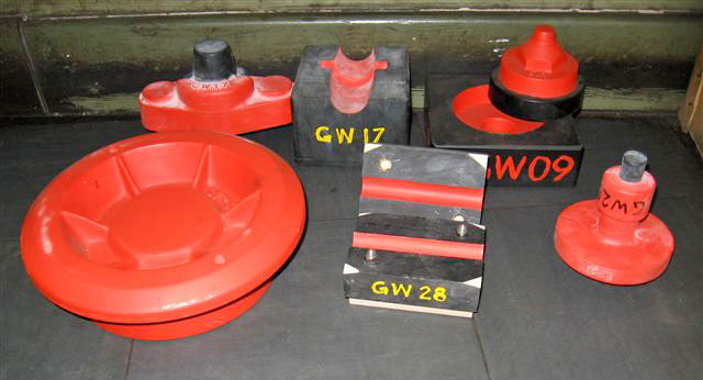
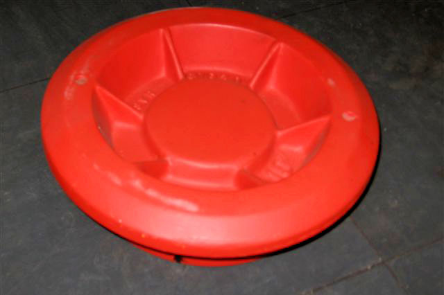
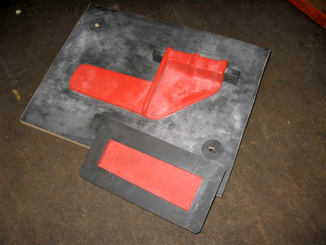
This group show a few patterns that we haven't pictured before: GW28 is a blower flange to suit 4566 and 7812. GW17 is a valve rod cover for 5532.
A close up of the valve cover.
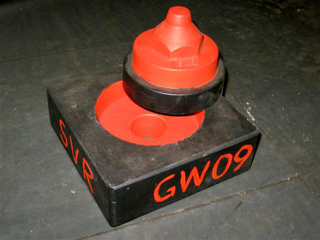
GW09 is a steam heat cap for 43106.
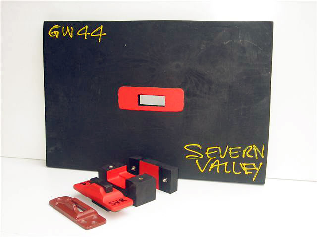
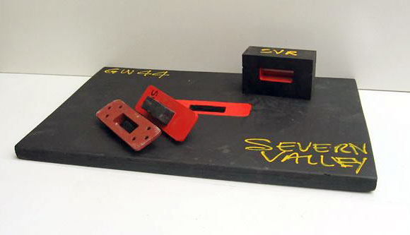
This pattern is a lamp iron converter that allows GW style lamps and headboards to be fitted onto LMS/BR lamp irons. |
|

| |
| © 2006-2008 GW(SVR) Association. Page created Feb 2008, last updated: 24 December, 2008 Webmaster |